Welcome to Your STM32 Journey
Welcome to the ultimate STM32 mastery series! Over the next 5 days, we'll transform you from a complete beginner to someone who can confidently build professional STM32 projects. This comprehensive journey covers everything from basic GPIO to advanced features like ADC, DMA, and real-time operating systems.
Why STM32?
- Industry Standard: Used in automotive, industrial automation, IoT devices, and consumer electronics
- Powerful ARM Cortex-M Core: 32-bit processing with excellent performance
- Rich Peripheral Set: Timers, ADC, DAC, communication interfaces (UART, I2C, SPI), and more
- Excellent Ecosystem: Free development tools, extensive documentation, and active community
- Scalable: From simple LED control to complex real-time systems
What You'll Learn
Day 1: Foundation & Setup
Architecture, IDE setup, LED blink
Day 2: GPIO & Interrupts
Button input, EXTI, debouncing
Day 3: Timers & PWM
Timer interrupts, PWM, servo control
Day 4: Communication
UART, I2C, SPI protocols
Day 5: Advanced Features
ADC, DAC, DMA, FreeRTOS
Hardware Requirements
- STM32 Development Board (STM32F103C8T6 "Blue Pill" or STM32 Nucleo)
- USB to Serial adapter (if using Blue Pill)
- Breadboard and jumper wires
- LEDs, resistors (220Ω), push buttons
- Optional: Servo motor, sensors (DHT11, LM35)
Software Requirements
- STM32CubeIDE (free, all-in-one development environment)
- STM32CubeMX (for peripheral configuration)
- ST-Link drivers
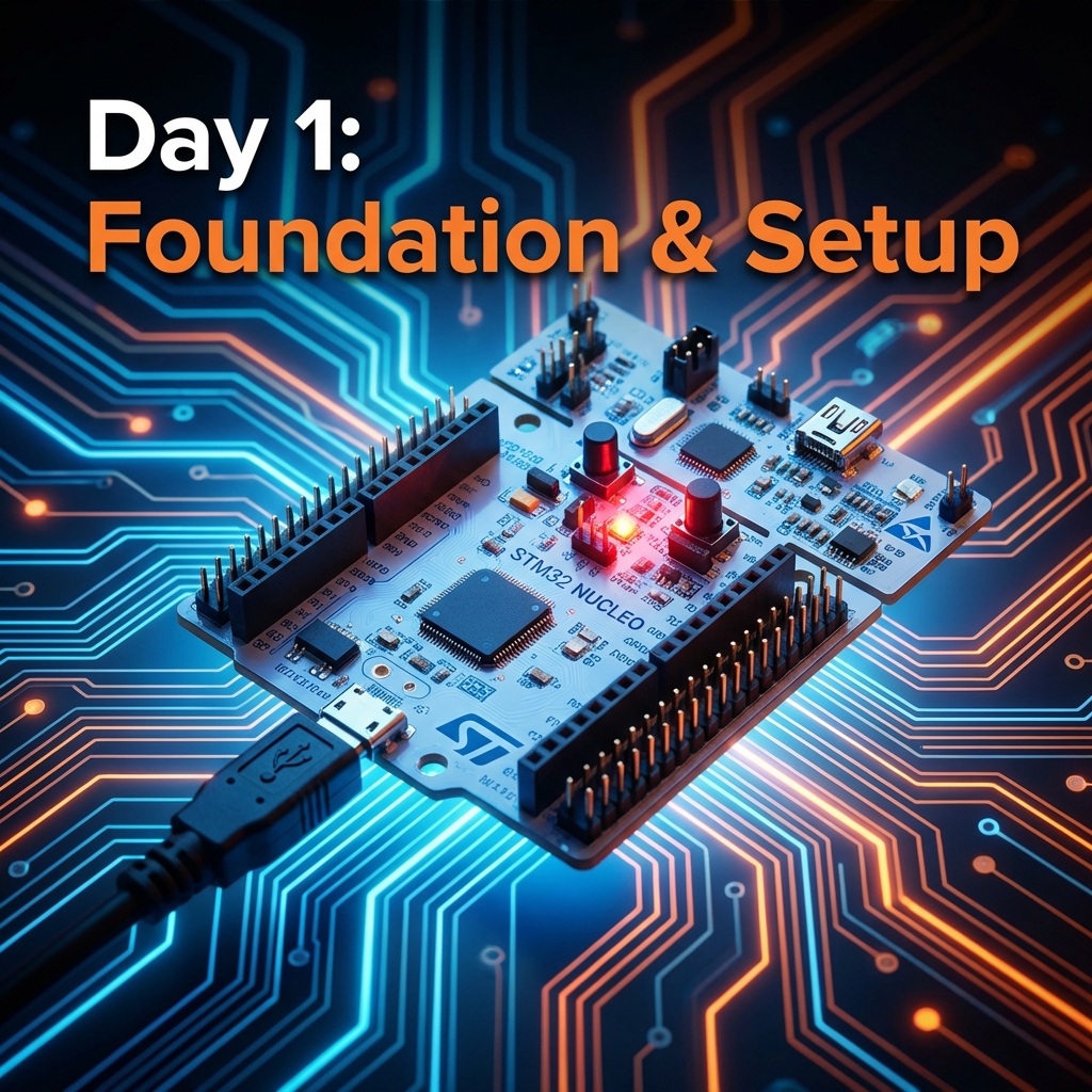
Day 1: Foundation & Setup
Today we're building the foundation for everything that follows. We'll understand STM32 architecture, set up your development environment, and write your first program to blink an LED - the "Hello World" of embedded systems.
Understanding STM32 Architecture
ARM Cortex-M Core
STM32 microcontrollers are built around ARM Cortex-M processors (M0, M3, M4, M7). These are 32-bit RISC processors optimized for embedded applications, offering excellent performance per watt.
Memory Organization
- Flash Memory: Stores your program code (typically 64KB-512KB)
- SRAM: Volatile memory for variables and stack (typically 20KB-128KB)
- System Memory: Contains bootloader for programming
Peripherals
STM32 boards come with rich peripherals: GPIO, Timers, ADC, DAC, UART, I2C, SPI, USB, CAN, and more.
Setting Up STM32CubeIDE
- Download STM32CubeIDE from ST's website
- Install and launch the IDE
- Create a new STM32 project
- Select your target board (e.g., STM32F103C8)
- Configure the project settings
Your First Program: LED Blink
/* USER CODE BEGIN WHILE */
while (1)
{
    HAL_GPIO_WritePin(GPIOC, GPIO_PIN_13, GPIO_PIN_SET);   // LED ON
    HAL_Delay(1000);                                        // Wait 1 second
    HAL_GPIO_WritePin(GPIOC, GPIO_PIN_13, GPIO_PIN_RESET); // LED OFF
    HAL_Delay(1000);                                        // Wait 1 second
    /* USER CODE END WHILE */
}
Key Concepts Learned
- STM32 architecture and memory organization
- Setting up development environment
- GPIO configuration and control
- HAL library basics
- Compiling and uploading code
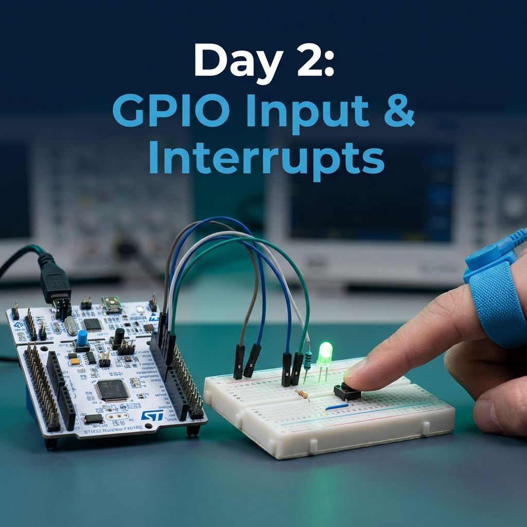
Day 2: GPIO Input & Interrupts
Today we level up from simple output to reading inputs and handling interrupts. You'll learn to read buttons, handle external interrupts, and build an interactive LED controller.
GPIO Input Modes
- Pull-up: Internal resistor pulls pin HIGH when button not pressed
- Pull-down: Internal resistor pulls pin LOW when button not pressed
- Floating: No internal resistor (requires external pull-up/down)
Reading Button State (Polling)
// Read button state
if (HAL_GPIO_ReadPin(GPIOA, GPIO_PIN_0) == GPIO_PIN_SET) {
    // Button pressed
    HAL_GPIO_WritePin(GPIOC, GPIO_PIN_13, GPIO_PIN_SET);
} else {
    // Button released
    HAL_GPIO_WritePin(GPIOC, GPIO_PIN_13, GPIO_PIN_RESET);
}
External Interrupts (EXTI)
Interrupts allow the MCU to respond immediately to events without constantly checking (polling). This is more efficient and enables faster response times.
Interrupt Callback
void HAL_GPIO_EXTI_Callback(uint16_t GPIO_Pin)
{
    if (GPIO_Pin == GPIO_PIN_0) {
        // Toggle LED on button press
        HAL_GPIO_TogglePin(GPIOC, GPIO_PIN_13);
    }
}
Debouncing Techniques
Mechanical buttons "bounce" - they make and break contact multiple times when pressed. We need to debounce to get clean button presses.
uint32_t lastDebounceTime = 0;
uint32_t debounceDelay = 50;  // 50ms

void HAL_GPIO_EXTI_Callback(uint16_t GPIO_Pin)
{
    uint32_t currentTime = HAL_GetTick();

    if ((currentTime - lastDebounceTime) > debounceDelay) {
        if (GPIO_Pin == GPIO_PIN_0) {
            HAL_GPIO_TogglePin(GPIOC, GPIO_PIN_13);
        }
        lastDebounceTime = currentTime;
    }
}
Advanced: Multi-Function Button
Let's build something more sophisticated! We can detect single press, double press, and long press events. Single press toggles the LED, double press activates blink mode, and long press turns everything off. This demonstrates state machines and advanced input handling.
Key Concepts Learned
- GPIO input configuration (pull-up, pull-down, floating)
- Polling vs. interrupts
- External interrupt (EXTI) configuration
- Debouncing techniques
- Building interactive applications
Practice Exercises
- Create a button that cycles through 3 LED brightness levels
- Implement a "press and hold" feature to gradually increase LED brightness
- Build a reaction time game where the LED turns on randomly and you measure button press speed
- Create a combination lock requiring a specific button press sequence to unlock the LED
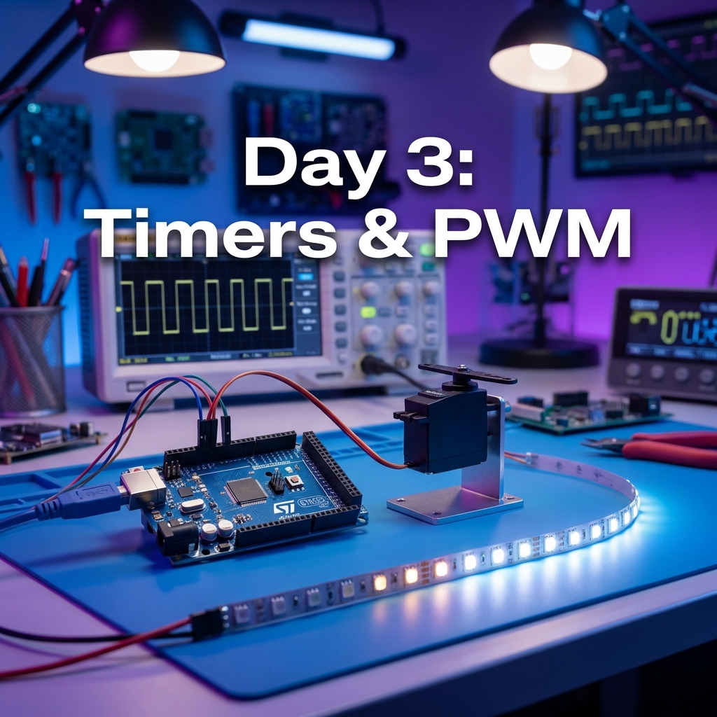
Day 3: Timers & PWM
Timers are the heartbeat of embedded systems. Today we'll master timer interrupts for non-blocking delays and PWM for controlling LED brightness and servo motors.
Understanding Timers
STM32 has multiple timer types: Basic, General-purpose, and Advanced. They can count up/down, generate interrupts, create PWM signals, and measure input signals.
Timer Calculation
// For 1 second interrupt with 72MHz clock:
// Prescaler = 7200 - 1  (72MHz / 7200 = 10kHz)
// Period = 10000 - 1     (10kHz / 10000 = 1Hz = 1 second)
Timer Interrupt for Non-Blocking Blink
void HAL_TIM_PeriodElapsedCallback(TIM_HandleTypeDef *htim)
{
    if (htim->Instance == TIM2) {
        HAL_GPIO_TogglePin(GPIOC, GPIO_PIN_13);
    }
}
PWM for LED Brightness Control
PWM (Pulse Width Modulation) varies the duty cycle to control average power. Perfect for LED dimming and motor speed control.
// Start PWM
HAL_TIM_PWM_Start(&htim3, TIM_CHANNEL_1);

// Set brightness (0-100%)
for (int brightness = 0; brightness <= 100; brightness++) {
    __HAL_TIM_SET_COMPARE(&htim3, TIM_CHANNEL_1, brightness);
    HAL_Delay(20);
}
Servo Motor Control
Servos use PWM with 50Hz frequency. Pulse width determines angle: 1ms = 0°, 1.5ms = 90°, 2ms = 180°.
void setServoAngle(uint8_t angle) {
    // Map angle (0-180) to pulse width (1000-2000 µs)
    uint16_t pulse = 1000 + (angle * 1000 / 180);
    __HAL_TIM_SET_COMPARE(&htim3, TIM_CHANNEL_1, pulse);
}
Input Capture: Frequency Measurement
Input capture allows you to measure pulse width, frequency, decode PWM signals, and read ultrasonic sensors. Configure TIM4 Channel 1 in input capture direct mode with prescaler 83 for 1MHz timer frequency. The timer captures the counter value when an input signal changes, allowing precise timing measurements.
Key Concepts Learned
- Timer architecture and configuration
- Timer interrupts for non-blocking delays
- PWM generation and duty cycle control
- Servo motor control with precise PWM
- Input capture for frequency and pulse width measurement
Practice Exercises
- Create a "breathing" LED effect with smooth PWM transitions
- Control 2 LEDs with different PWM frequencies
- Build an RGB LED controller using 3 PWM channels
- Create a servo-based "radar" scanner sweeping from 0 to 180 degrees
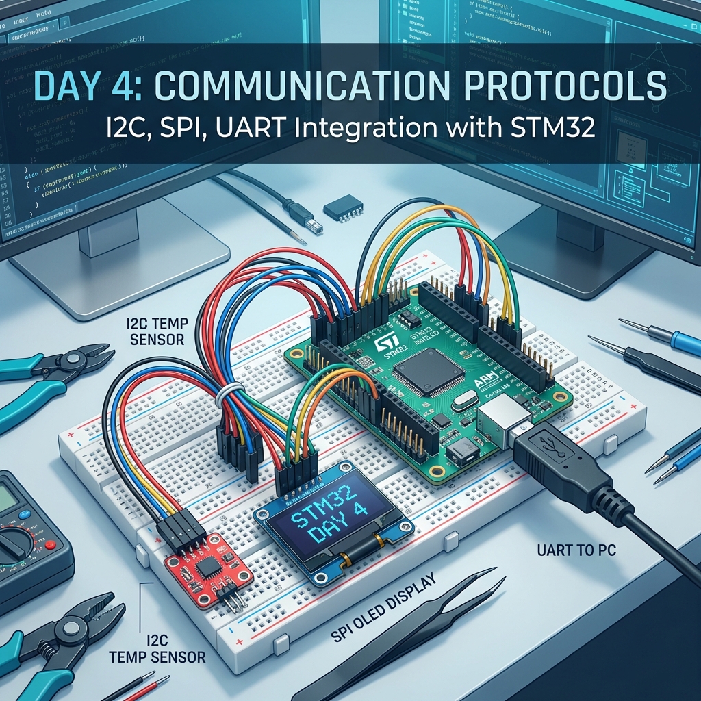
Day 4: Communication Protocols
Communication is key in embedded systems. Today we'll master UART, I2C, and SPI - the three most common protocols for interfacing with sensors, displays, and other devices.
Protocol Comparison
| Protocol | Wires | Speed | Use Case |
|---|---|---|---|
| UART | 2 (TX, RX) | 9600-115200 bps | Serial communication, debugging |
| I2C | 2 (SDA, SCL) | 100-400 kHz | Multiple sensors on same bus |
| SPI | 4 (MOSI, MISO, SCK, CS) | 1-10 MHz+ | High-speed displays, SD cards |
UART Communication
// Send string via UART
char msg[] = "Hello from STM32!\r\n";
HAL_UART_Transmit(&huart1, (uint8_t*)msg, strlen(msg), HAL_MAX_DELAY);

// Receive data
uint8_t rxData;
HAL_UART_Receive(&huart1, &rxData, 1, HAL_MAX_DELAY);
I2C Temperature Sensor
#define LM75_ADDRESS 0x48 << 1  // I2C address (shifted for HAL)

// Read temperature
uint8_t tempData[2];
HAL_I2C_Mem_Read(&hi2c1, LM75_ADDRESS, 0x00, 1, tempData, 2, HAL_MAX_DELAY);

// Convert to Celsius
int16_t temp = (tempData[0] << 8) | tempData[1];
float temperature = temp / 256.0;
SPI Display Interface
// Send command to SPI display
void sendCommand(uint8_t cmd) {
    HAL_GPIO_WritePin(DC_GPIO_Port, DC_Pin, GPIO_PIN_RESET);  // Command mode
    HAL_GPIO_WritePin(CS_GPIO_Port, CS_Pin, GPIO_PIN_RESET);  // Select device
    HAL_SPI_Transmit(&hspi1, &cmd, 1, HAL_MAX_DELAY);
    HAL_GPIO_WritePin(CS_GPIO_Port, CS_Pin, GPIO_PIN_SET);    // Deselect
}
Choosing the Right Protocol
Use UART when you need simple point-to-point communication, debugging output to a PC, GPS module communication, or Bluetooth module interfacing. Choose I2C when connecting multiple sensors on one bus, using EEPROMs or RTCs, dealing with limited GPIO pins, or when moderate speed is acceptable. Select SPI for high-speed data transfer, driving displays (OLED, LCD, TFT), SD card communication, or when you have enough GPIO pins available.
Key Concepts Learned
- UART for serial communication and debugging
- I2C for multi-device communication
- SPI for high-speed data transfer
- Protocol selection based on requirements
- Real sensor and display interfacing
Practice Exercises
- Build a UART command interpreter that responds to text commands
- Create an I2C device scanner that lists all connected devices
- Display sensor data on an OLED screen using SPI or I2C
- Build a data logger that records sensor readings via UART
Day 5: Advanced Features & Complete Project
Welcome to the final day! We'll explore advanced features like ADC, DAC, DMA, and low power modes. Then we'll build a complete Weather Station project integrating everything you've learned.
Analog-to-Digital Converter (ADC)
ADC converts analog signals (0-3.3V) to digital values (0-4095 for 12-bit ADC). Essential for reading sensors like temperature, light, potentiometers.
// Read ADC value
HAL_ADC_Start(&hadc1);
HAL_ADC_PollForConversion(&hadc1, HAL_MAX_DELAY);
uint32_t adcValue = HAL_ADC_GetValue(&hadc1);

// Convert to voltage
float voltage = (adcValue * 3.3) / 4095.0;
Digital-to-Analog Converter (DAC)
DAC converts digital values to analog voltages. Used for audio, waveform generation, and analog control signals.
// Generate sine wave
for (int i = 0; i < 360; i++) {
    float sine = sin(i * 3.14159 / 180.0);
    uint32_t dacValue = (uint32_t)((sine + 1) * 2047.5);
    HAL_DAC_SetValue(&hdac, DAC_CHANNEL_1, DAC_ALIGN_12B_R, dacValue);
    HAL_Delay(10);
}
Direct Memory Access (DMA)
DMA transfers data between peripherals and memory without CPU intervention, freeing the CPU for other tasks.
// UART transmit with DMA
char msg[] = "DMA Transfer!\r\n";
HAL_UART_Transmit_DMA(&huart1, (uint8_t*)msg, strlen(msg));

// ADC continuous conversion with DMA
uint16_t adcBuffer[100];
HAL_ADC_Start_DMA(&hadc1, (uint32_t*)adcBuffer, 100);
Low Power Modes
STM32 offers multiple power modes: Run mode (highest power, all clocks running), Sleep mode (fast wake-up, CPU off but peripherals on), Stop mode (medium wake-up, most clocks off, low power), and Standby mode (slow wake-up, almost everything off, lowest power). Use Sleep mode for short idle periods, Stop mode for longer idle with quick wake-up needed, and Standby for maximum power saving when wake-up time isn't critical.
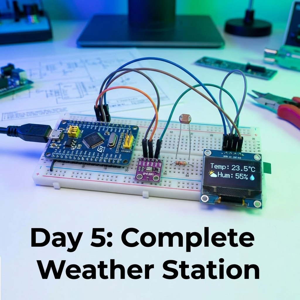
Complete Weather Station Project
Let's integrate everything: ADC for temperature sensor, I2C for humidity sensor, UART for data logging, and PWM for fan control.
while (1) {
    // Read temperature (ADC)
    float temp = readTemperature();

    // Read humidity (I2C)
    float humidity = readHumidity();

    // Log data (UART)
    char buffer[50];
    sprintf(buffer, "Temp: %.1f°C, Humidity: %.1f%%\r\n", temp, humidity);
    HAL_UART_Transmit(&huart1, (uint8_t*)buffer, strlen(buffer), HAL_MAX_DELAY);

    // Control fan based on temperature (PWM)
    if (temp > 30) {
        setFanSpeed(100);  // Full speed
    } else if (temp > 25) {
        setFanSpeed(50);   // Half speed
    } else {
        setFanSpeed(0);    // Off
    }

    HAL_Delay(5000);  // Update every 5 seconds
}
Introduction to FreeRTOS
FreeRTOS is a real-time operating system for microcontrollers. It enables multitasking, allowing multiple tasks to run "simultaneously."
// Task 1: Blink LED
void vTask1(void *pvParameters) {
    while(1) {
        HAL_GPIO_TogglePin(GPIOC, GPIO_PIN_13);
        vTaskDelay(pdMS_TO_TICKS(1000));
    }
}

// Task 2: Read sensor
void vTask2(void *pvParameters) {
    while(1) {
        float temp = readTemperature();
        vTaskDelay(pdMS_TO_TICKS(5000));
    }
}
Key Concepts Learned
- ADC for analog sensor reading
- DAC for waveform generation
- DMA for efficient data transfer
- Low power modes for battery applications
- Building complete integrated projects
- Introduction to FreeRTOS multitasking
Final Challenge
Build a Smart Home Controller with temperature/humidity monitoring, light level detection and automatic lighting, motor control for fans, OLED display for status, UART control interface, data logging to SD card, and low power sleep mode for energy efficiency. Share your projects with the community!
🎉 Congratulations!
You've completed the 5-day STM32 mastery journey! You've learned everything from basic GPIO to advanced features like ADC, DMA, and FreeRTOS. You're now equipped to build professional embedded systems projects.
Next Steps
- Build your own projects combining multiple concepts
- Explore advanced topics: CAN bus, USB, Ethernet
- Learn about low-level register programming
- Dive deeper into FreeRTOS and real-time systems
- Join STM32 community forums and share your projects